6 Welding
16.1 Introduction
Recall movies you have watched showing Vikings or Samurai wielding swords. Now think of walking through a large city and looking up at the skyscrapers, driving your car or riding a bus over a bridge, opening your refrigerator, and cracking open a soft drink can. One thing all of these objects have in common is they are made of metals-even concrete structures are reinforced with steel. Indeed, if we did not have the technology to make things out of metals we would still be living in the Stone Age. All of this metal needs methods to be joined together, in this chapter we will cover the common ways in which metal is joined together (Rupik, et al).
Joining is an important process in a number of industries, such as aerospace, automotive, oil, and gas. Many products cannot be fabricated as a single piece, so components are fabricated first and assembled later. Joining technology can be classified as a liquid-solid-state process and mechanical means. Liquid-solid-state joining includes welding, brazing, soldering, and adhesive bonding. Mechanical joining includes fasteners, bolts, nuts, and screws (Ishak 1).

16.2 Learning Objectives
After completing this chapter, you will be able to:
- Explain the principles of welding
- Understand the differences between the major types of welding processes including MIG, TIG, laser welding, and friction stir welding
- Distinguish between different weld configurations including the five basic weld joint types (butt, T, lap, edge, and corner), groove welds, fillet welds, and plug/slot welds
- Understand basic design considerations for welded components, including material compatibility, equipment accessibility, and joint alignment
These objectives will provide you with a solid foundation in welding technology
16.3 Fundamentals of Welding
Fusion welding is known as non-pressure welding, in which edge samples to be joined with the filler metal are heated above the melting points to create a weld pool and allow solidification. Gas tungsten arc welding (GTAW) aka tungsten inert gas (TIG) and gas metal arc welding (GMAW) aka metal inert gas (MIG) are categorized under fusion welding. GTAW and GMAW are mostly used by the welder to weld both ferrous and non-ferrous metals. In fusion welding, inert gases, such as argon (Ar), helium (He), and carbon dioxide (CO2), are used for surrounding the electrode and molten metal from the welded metal. These inert gases will eliminate the formation of metal oxides and nitrides, which can lower the ductility and toughness of the welded metal (Ishak 2).
Another common type of welding is laser welding, Laser welding has shown remarkable progress as a high-efficiency welding technique through the years. The process of Laser welding for metal is based on melting metal under a highly concentrated beam of radiation that is focused on the surface metal to join two parts. Radiation is partially absorbed by the upper layer of the metal, causing it to heat to the melting point (Ishak 2).
16.4.1 GMAW/MIG Welding
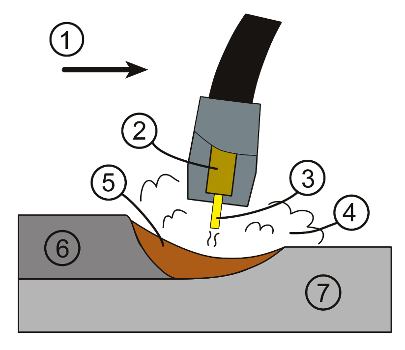
GMAW is also known as metal inert gas (MIG) welding in which an external gas, such as argon, helium, carbon dioxide, argon + oxygen, and other gas mixtures, is used as a shielding gas. Consumable electrode wire, having the same or approximate chemical composition to that of parent metal, is continuously fed from a spool to the arc zone. The arc from the welding parameters (voltage and current) heats and melts the samples’ edges and the filler wire. The fused filler metal is supplied to the surface of the workpiece, fills the weld pools, and forms the joint between the workpieces similarly or dissimilarly. The overall process in GMAW is described as a semi-automatic method because of the automatic feeding of the filler rod while the welder controls only the position and speed of the torch. GMAW can weld almost all metals and alloys, aluminum alloys, and stainless steel (Ishak 2).
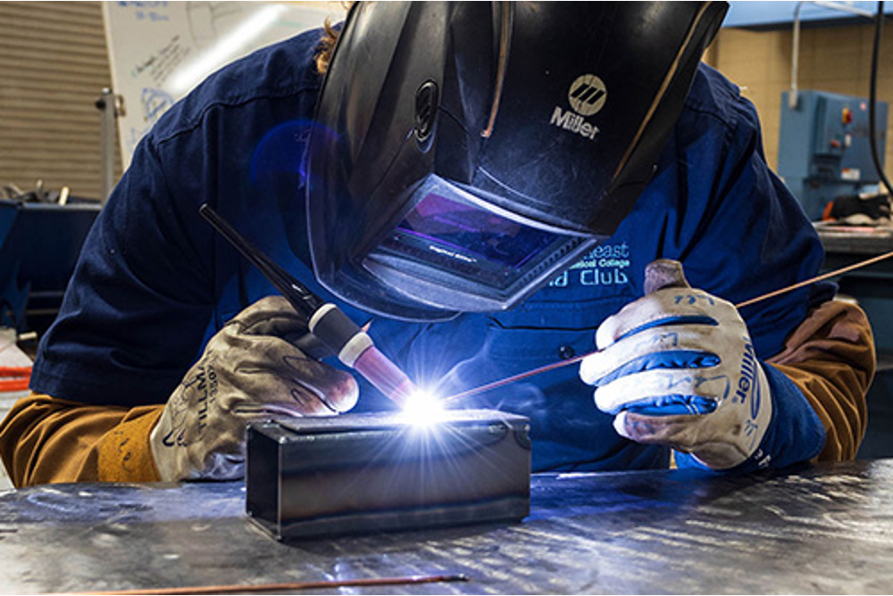
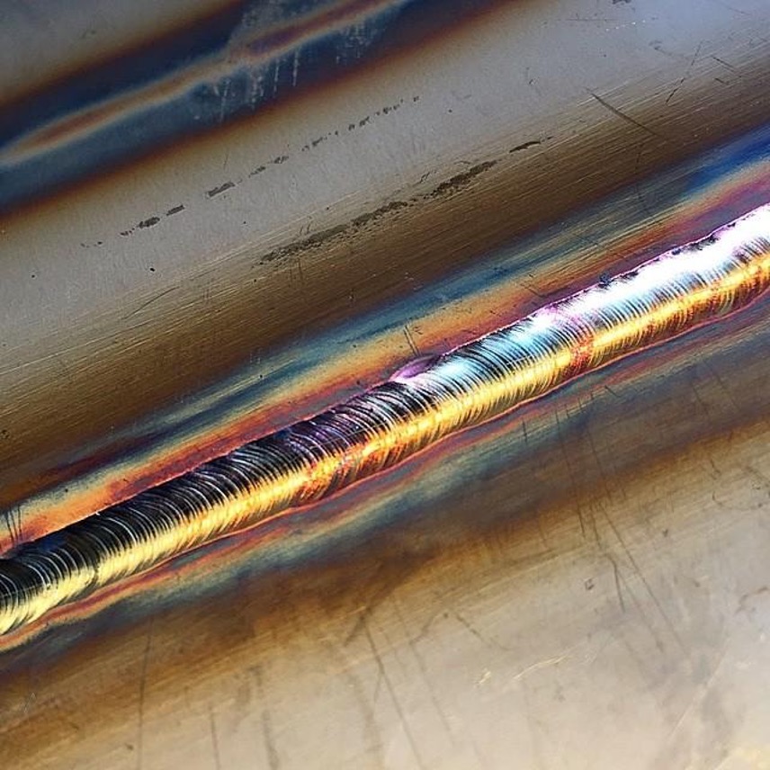
16.4.2 GTAW / TIG Welding
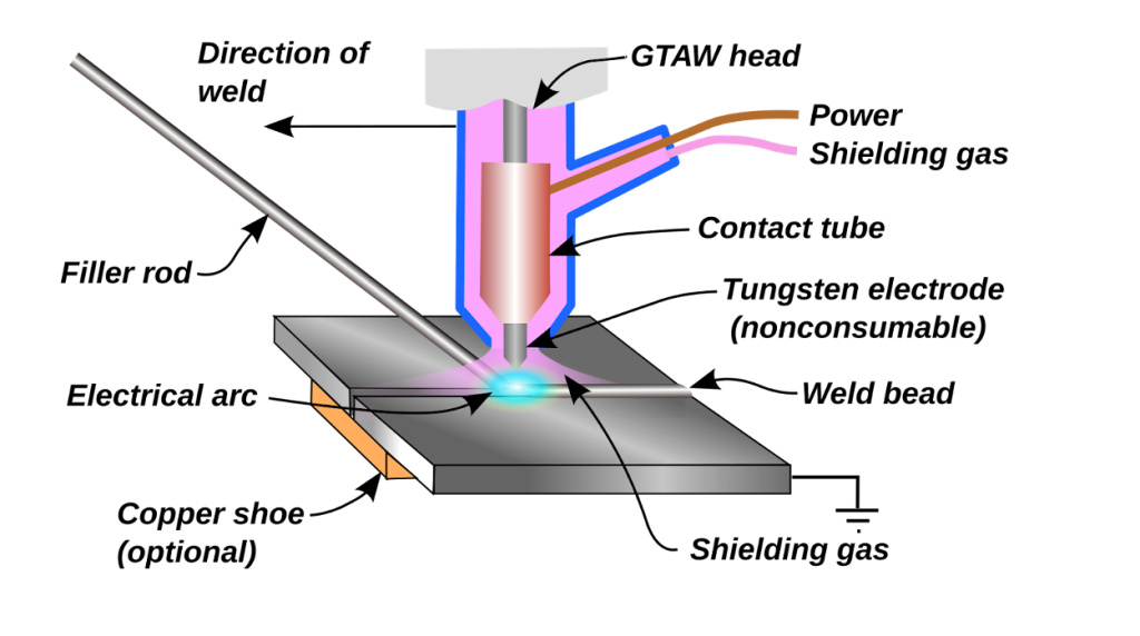
GTAW is also known as tungsten inert gas (TIG) welding, in which heat from an electric arc is used. The arc sparks between a tungsten non-consumable electrode and the workpiece. The molten pool is shielded by an inert gas such as argon, helium, and nitrogen. The shielding gas prevents the molten pool from atmospheric contamination. The heat produced by the arc melts the samples’ edges. The filler rod can be used if required, especially in welding aluminum. GTAW produces a high-quality weld of most metals because it does not use flux. An externally supplied shielding gas is necessary because of the high temperatures involved to prevent metal from oxidation. Direct current is typically used, and its polarity is important as this welding method still uses current and voltage as critical parameters. Given that the tungsten electrode is not consumed during welding, a stable and constant arc is preserved at a constant current level. The filler metals used are usually similar to the parent metals to be welded, without using flux. The shielding gas used is normally argon or helium (or a mixture of gases). GTAW is used for a wide variety of metals and applications. Metals that usually can be welded by GTAW are aluminum, magnesium, titanium, and copper and its alloy. The tungsten electrode is usually in contact with a water-cooled copper tube (contact tube), which is connected to the welding cable from the terminals. Both the weld current and electrode must be cooled to avoid overheating during welding (Ishak 2).
16.4.3 Laser Welding
Laser welding has shown remarkable progress as a high-efficiency welding technique through the years. The process of Laser welding for metal is based on melting metal under a highly concentrated beam of radiation that is focused on the surface metal to join two parts. Radiation is partially absorbed by the upper layer of the metal, causing it to heat to the melting point. The important processing parameters involved in laser welding include laser properties (average and peak power, beam quality, beam diameter, wavelength, and focal length), weld setting (focus position toward the material surface, weld type, and shielding gas), and physical properties of the parent metal. There are two types of welding area, namely conduction or keyhole mode. The obvious width and depth difference in this welding area is due to the energy (E) and peak power density (PPD) applied. Laser welding has many advantages over the conventional joining method, such as deep penetration, low heat input, small heat-affected zone (HAZ), and high speed. In terms of production, some of the advantages of laser welding are high speed, high process productivity, flexibility in control, and automation. Three common types of laser machines, namely CO2, YAG, and fiber lasers, are widely used in the industry for welding purposes. CO2 is known as a gas laser with a wider wavelength compared with solid-state lasers: YAG and fiber lasers. Unlike solid-state lasers, the wide wavelength of the CO2 laser results in poor absorption by a wide range of materials. Meanwhile, the fiber laser presents several advantages over the YAG laser because of the former’s compact design, good beam quality, and low cost of ownership and maintenance (Ishak 3).
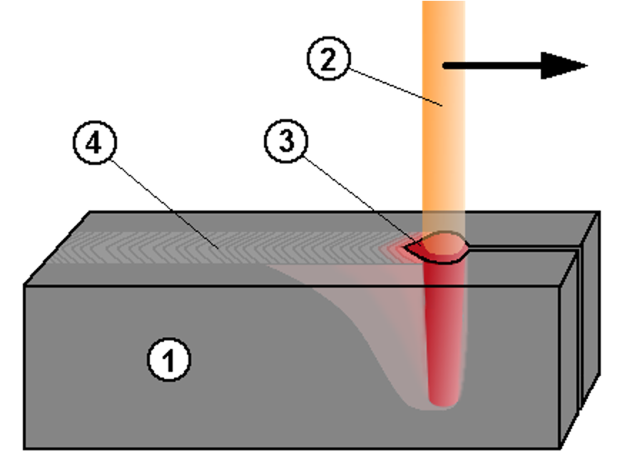
1. object 2. energy ray 3. keyhole 4. Weld
16.4.4 Friction stir welding
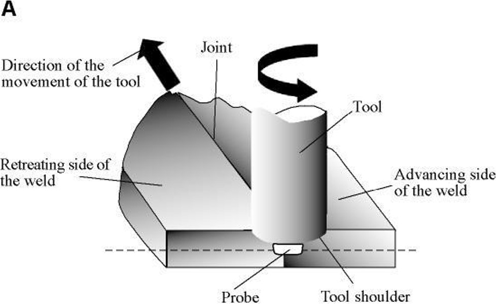
FSW is a welding process that involves solid-state joining; this process has expanded rapidly since its development in 1991 by The Welding Institute, UK. FSW is a solid-state welding technique that does not involve melting and occurs below the melting point. It uses a rotating tool to generate necessary heat for welding. This tool consists of three parts: the shank, shoulder, and pin. The shank is the part where the tool is attached to the FSW machine, whereas the shoulder and pin are attached to the workpiece. The shoulder and pin provide additional frictional treatment and prevent the plasticized material from escaping from the weld region. During FSW, the rotating tool moves along the joint of two plates that generate heat. This tool then recirculates flow of the plasticized material near the tool surface. The size of the tool shoulder is larger than that of the pin tool. The FSW tool serves two main functions, namely workpiece heating and material movement to produce a joint. Heating is produced by friction of the pin and workpiece and plastic deformation of the workpiece. The heat that is produced will soften the material around the pin, and tool rotation will move the material from the front of the pin to the back of the pin. The result of this process is a joint produced in solid state. FSW can be utilized in a wide variety of industries, such as automotive, aerospace, maritime, and railway. FSW has been considered the most substantial joining process in the past decade because it offers many advantages such as energy efficiency, environmental friendliness, and versatility. Compared with arc welding, FSW uses less energy and does not require a shielding gas and flux, thereby making this process an eco-friendly one. This joining process does not need any filler, so it is suitable to join many types of dissimilar metals. FSW is a technique that can avoid drawbacks from common fusion welding because FSW can be conducted under solid state. Several problems (e.g., spatter, hot cracking, and distortion) in other types of welding are eliminated by using FSW. Defects such as voids, lack of penetration, and broken surface can be minimized by using this welding technique (Ishak 3).
16.5 Basic Weld Identification
16.5.1 Weld Joints
A weld joint is the junction of two workpieces to be joined by welding, or in some cases brazing. There are five basic joint types (Rupik et. al 15.1).
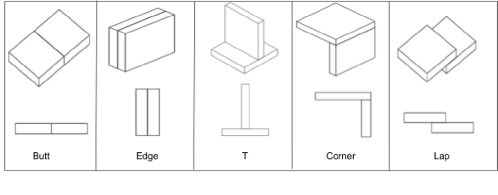
- A Butt Joint is created when two workpieces are butted against each other along their thickness; their surfaces will typically lie in a common plane.
- A T Joint is created when the edge of one workpiece abuts the surface of the other, creating a T shape. It is most common for the workpieces to be perpendicular, but in some cases, the abutting member may be skewed at an angle, referred to as a skewed T joint.
- A Lap Joint is a joint configuration in which the surfaces of the two workpieces lie in close contact, and neither of their edges abut the other.
- An Edge Joint is created when the surfaces of two workpieces lie parallel or nearly parallel, and their edges lie in a nearly common plane. Welding in these joints takes place at the junction of the two edges.
- In a Corner Joint, the two workpieces form an L shape. There are three possible configurations for a corner joint. In an open corner joint, the edges of the workpieces do not overlap at all.
- In a closed, sometimes called flush, corner joint, the surface of one workpiece completely overlaps the edge of the other. The joint may also be half-open, where the surface of one workpiece only partially overlaps the edge of the other. (Rupik et. al 15.1)
16.5.2 Groove Welds
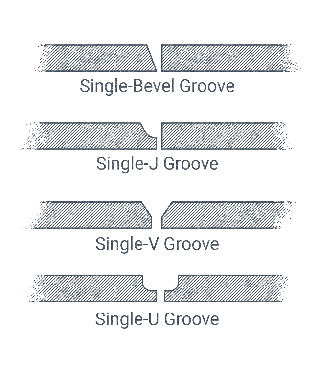
In manual and semi-automatic arc welding processes, groove welds are probably the most widely produced welds, with fillet welds, the next type of weld discussed, coming in a close second. Groove welds apply to all five basic weld joints discussed above (Rupik et. al 15.2).
With the exception of a square groove weld, most groove welds require some sort of special cut through the thickness of the workpiece. In industry, these cuts are sometimes colloquially referred to as an edge preparation. These cuts increase the penetration of the weld into the material and increase weld strength. Figure 15.5 is a chart illustrating the geometry of the different types of groove weld joints. There are many groove preparations that may be cut into the edges of workpieces, with different advantages, disadvantages, and applications. These different joint preparations also have a variety of terms to describe them and dimensions to measure them (Rupik et. al 15.2).
16.5.3 Fillet Welds
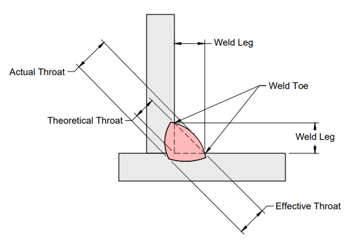
A fillet weld is extremely common in arc welding, and though they are distinct from groove welds some of the terminology crosses over. Fillet welds do not involve any sort of edge preparation or beveling. Instead, fillet welds are the result of depositing a weld at the intersection of two perpendicular surfaces, resulting in a weld bead with a triangular cross-section, as shown above. It is not ideal for a fillet weld to have any sort of root opening, though in some cases, a small opening is tolerable (Rupik et. al 15.3).
Fillet welds are common because they are economical. Without the need for any beveling or special joint preparation, they can vastly reduce production time. There are some limitations (Rupik et. al 15.3).
Because a fillet weld only exists in between two 90o surfaces it cannot be applied to all joints. T joints, lap joints, and open or half-open corner joints can all have fillet welds applied to them. An edge joint and closed corner joint can only be groove welded. They could be applied in butt joints if the two parts had considerably different thicknesses or are overlapped by a 3rd and 4th part creating what is called a splice joint (Rupik et. al 15.3).
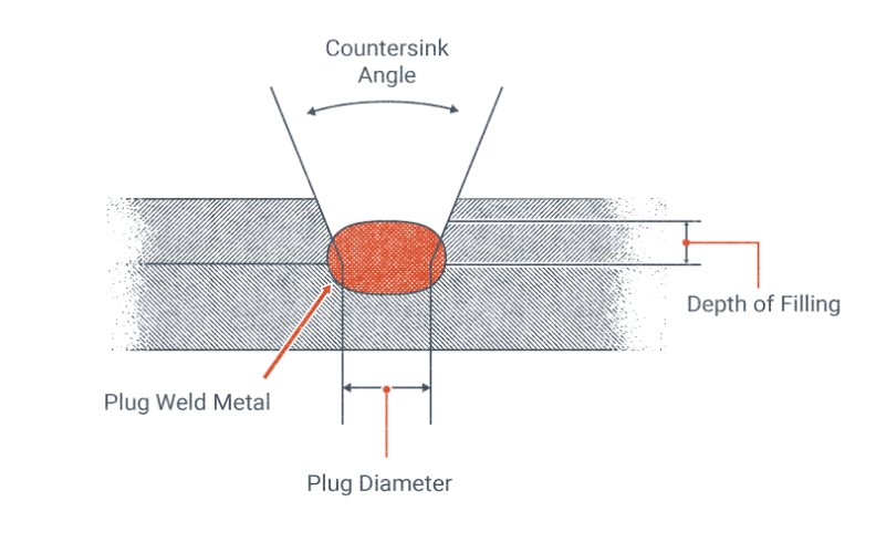
16.5.4 Plug and Slot Welds
A plug or slot weld is used quite often in arc welding. These types of welds may only be applied in lap joints, so they are not as common as groove or fillet welds. A plug weld is a weld made through a hole in one of two overlapping parts, joining them together. A slot weld is the same concept, only with the hole being elongated increasing the area where the two parts are fused (Rupik et. al 15.4).
16.6 Basic Design Considerations
When designing a welded part, one should start the design with welding in mind not thinking about other metal forming methods such as casting. Additionally, when creating a design think about where instead of welding, other more economical methods can be used, such as instead of using a welded corner joint, having the metal bent to achieve the same corner feature. When designing a part to be arc-welded, consider how the piece will be welded together, such as leaving enough room for the welding gun to be used, and ensuring that the angle at which the torch has to be held isn’t too extreme. In general MIG welding torches take up more space than TIG torches, but either way, space must be left. Additionally, you want to create a design where the welder is welding on a flat horizontal surface as much as possible because this is the easiest position to weld. How well the pieces of a component line up has a significant effect on the outcome of the welding process, a large gap between pieces will decrease the weld quality. While pieces of different thicknesses can be welded together, joining pieces of the same thickness optimizes the quality of the weld. The same is true for welding different materials, it is possible to weld different materials but additional considerations must be taken into account such as corrosion and differences in how the metals react to heat from welding. It is a good idea to have the shop that will be doing the welding look over your design before production to help with any considerations specific to their equipment.
16.7 Chapter Summary
In this chapter, we covered the fundamental principles and applications of welding.
We covered several of the most common welding methods, including GMAW aka MIG welding, GTAW aka TIG, laser welding, and friction stir welding.
The chapter also provided an overview of the common types of welds, including five basic joint types: butt, T, lap, edge, and corner joints. Along with groove welds, fillet welds, and plug/slot welds, including their characteristics, applications, and specific considerations for each.
Finally, we covered design considerations for welded components, including the importance of planning for weldability from the start of creating a design. This included practical considerations such as equipment accessibility, material compatibility, and joint alignment. These fundamentals provide a foundation for understanding the technical aspects of welding and the process of designing welded parts.
16.8 References
Lake Washington Institute of Technology Welding Department. Wire Feed Welding. OpenWA.
Moran, Cameren. Interpretation of Metal Fab Drawings. Open Oregon Educational Resources, 2017. Accessed 6 February 2025.
Rupik, Douglas, et al. Introduction to Welding. Washington State Board for Community and Technical Colleges.
Ishak, Mahadzir, editor. Joining Technologies. IntechOpen, 2016. Accessed 11 February 2025.
Groover, Mikell P. Fundamentals of Modern Manufacturing: Materials, Processes, and Systems. Wiley, 2015.
Media Attributions
- steel bridge © Isaiah V is licensed under a CC BY-NC-SA (Attribution NonCommercial ShareAlike) license
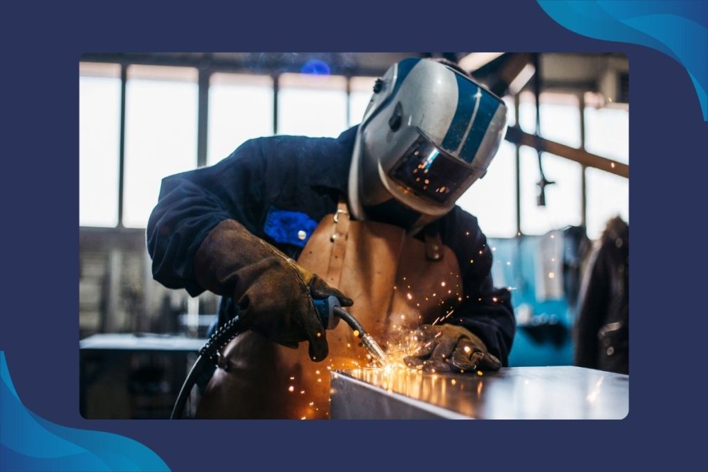
- welders © Keller Insurance Services is licensed under a CC BY-NC (Attribution NonCommercial) license
- weld pool © Spangineer is licensed under a CC BY-SA (Attribution ShareAlike) license
- tig © Duk is licensed under a CC BY-SA (Attribution ShareAlike) license
- laser weld © Erik Wannee is licensed under a CC0 (Creative Commons Zero) license
- friction stir © Anandwiki is licensed under a CC BY-SA (Attribution ShareAlike) license
- basic weld joint types © Cameron Kjeldgaard is licensed under a CC BY (Attribution) license
- weld groves © Nicholas Malara is licensed under a CC BY (Attribution) license
- fillet weld © Cameron Kjeldgaard is licensed under a CC BY (Attribution) license
- plug weld © Nicholas Malara is licensed under a CC BY (Attribution) license
- TIG © Reza Nouri Shirazei is licensed under a CC BY-SA (Attribution ShareAlike) license
- weld_joint © Joel Washing is licensed under a CC BY (Attribution) license
