7 Mechanical Assembly
18.1 Introduction
Mechanical assembly is the joining of two or more parts with mechanical fasteners. Mechanical fasteners such as screws, nuts and bolts create a non-permanent fastened joint permitting future disassembly and reassembly of the component.
Mechanical fasteners such as rivets and eyelets create a fastened permanent joint. Mechanical interference is another assembly method where two mating parts are joined together. The interference holds the parts together. Mechanical interference methods include press fitting, snap fits and shrink and expansion fits.
Many factors must be taken into consideration when designing and assembling with fasteners. This includes the stresses that result from static and dynamic (fatigue) loading, dimensions of the fastener, the quantity used, material properties, safety, cost and whether assembly and disassembly is desired.
18.2 Learning Objectives
Gain an understanding of the various hardware components (fasteners) that are used in mechanical assembly. The methods and tools that are used during assembly and to gain knowledge of basic design factors for bolts and rivets.
18.3 Non-Permanent Joints
Non-permanent joints are joints between two or more parts or components that can be undone and redone. Non-permanent joints can be fastened with screw, bolts and nuts or held together with removable press fits.
18.3.1 Screws, Bolts and Nuts
Threaded fasteners enable assembly and disassembly of the parts without damaging them. A common type of threaded fastener is a bolt, which is a cylindrical rod with a head at one end and a thread at the other end. Bolts are used with nuts, which are also threaded devices that fit onto the bolts and tighten them. Bolts and nuts have different grades, which indicate their strength and resistance to various loads and environments. The grades are defined by standards organizations such as the Society of Automotive Engineers (SAE), the Society for Testing and Materials (ASTM), and the International Organization for Standardization (ISO). Some examples of bolt types are round head bolts, which have a dome-shaped head, and studs, which have threads on both ends. Some examples of nut types are square nuts, which have four flat sides, and hex nuts, which have six flat sides. Nuts can also be single-threaded or double-threaded, depending on whether they have one or two threads per inch.
Another type of threaded fastener is a screw, which is similar to a bolt but has a pointed tip and is usually driven into a pre-drilled hole in the component. Screws can also be used with nuts or washers to increase their clamping force or prevent loosening. Screws have various types, depending on their function and design. Some examples are machine screws are: cap screws, which have a cylindrical head with a hexagonal or socket shape; set screws, which have no head and are used to secure a shaft or collar; Sems screws, which have a washer attached; and tapping screws, which create their own threads in the component as they are driven in. Screws also have various heads and tip end conditions, depending on how they are driven and what kind of hole they fit it into. Some examples of screw heads are slotted, Phillips, hexagonal, and Torx. Some examples of tip end conditions are blunt, pointed, self-drilling, and self-tapping.
18.3.2 Thread Standards and Definitions
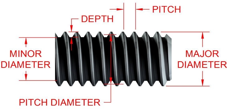
Pitch
Pitch is the distance between two adjacent threads measured along the axis of the fastener. The pitch in U.S. units is the reciprocal of the number of thread forms per inch N.
Major Diameter
Major Diameter is the largest diameter of a screw thread.
Minor Diameter
Minor (root) Diameter is the smallest diameter of a screw thread.
Lead
Lead is the distance that the fastener advances along its axis in one turn. For a single thread like the example pictured below, the lead is the same as the pitch.
Metric Threads
Metric threads are specified by writing the diameter and pitch in millimeters, in that order. Example, M12 x 1.75 is a metric thread with a nominal major diameter of 12mm and a pitch of 1.75mm. The letter M indicates the metric designation
Unified Threads
Unified Threads are specified by stating the nominal major diameter, the number of threads per inch, and the thread series. Example, 5/8 in-18 UNRF.
Common Thread Types
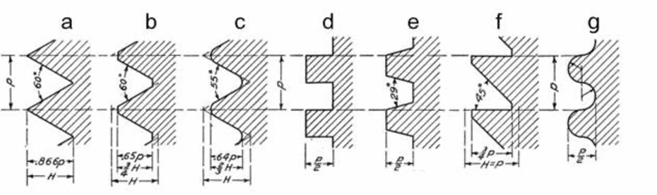
(b) American National thread – Similar to today’s Unified thread
(c) Whitworth or British Standard thread
(d) Square thread
(e) Acme thread
(f) Buttress thread
(g) Knuckle thread
Square Threads

18.3.2 Threaded Fasteners

18.4 Permanent Joints
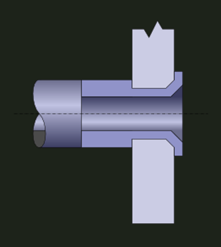
18.4.1 Rivets
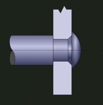
A rivet is another type of discrete fastener that consists of a cylindrical shaft with a head at one end and a tail at the other end. Rivets are used to join two or more components together by inserting them through holes in the components and deforming the tail to form another head on the opposite side. Rivets can be made of various materials such as steel, aluminum, copper, or plastic. Rivets have some advantages over threaded fasteners such as being cheaper, lighter, more resistant to vibration and corrosion, and more aesthetically pleasing. However, rivets also have some limitations such as being permanent (cannot be disassembled without damaging them), requiring access to both sides of the components such as with solid rivets (cannot be used in blind holes), requiring special tools for installation and removal (such as hammers or rivet guns), and having lower strength than some threaded fasteners.
18.4.2 Eyelets
Eyelets like rivets are permanent and cannot be dissembled. They are thin- walled tubular fasteners with a flange on one end and are usually made from sheet metal. Eyelets can substitute rivets in applications where stress is lower to save material, weight and costs.
18.4.1 Press Fit
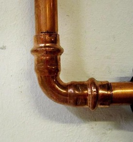
Press Fitting also known as friction fit is the fitting of two parts that are held together by friction after being pushed together.
18.4.2 Shrink and Expansion Fits
Shrink and expansion fitting is the assembly of two parts (typically a pin or shaft inserted into a collar) that have an interference fit at room temperature. Prior to assembly one of the parts is either heated or cooled allowing for ease of fit, then brought back to room temperature forming a strong interference fit. Shrink fitting is the heating of a part prior to assembly allowing for expansion. The parts are assembled together and the heated part is allowed to cool (shrink) to room temperature. Opposite of this is expansion fitting where a part is cooled prior to assembly than allowed to return to room temperature (expand).
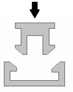
18.4.3 Snap Fits
Snap fits are two parts that are designed to interlock together with applied pressure and maintain the assembly once together. Snap fits are not total interference since a slight interference exists after assembly.
18.5 Design and Assembly
18.5.1 Bolt and Member Stiffness
Bolt stiffness (kb) can be modeled using the formulation below, where E is the elastic modulus of the bolt material:
$$ k_b = \frac{A_d A_t E}{A_d l_t + A_t l_d} $$
Effective bolt spring rate (km) can be calculated using the equation below:
$$ k_b = \frac{0.5574\pi E_d}{2ln(5\frac{0.5574l + 0.5d}{0.5774l + 2.5d})} $$
Where kb is the spring rate or effective stiffness of the bolt in the clamped zone and km is the spring rate of the material that is clamped.
18.5.2 Static Loading in Tension with Preload
It is recommended that bolts should be tightened with an initial tension (preload) to 75% of their proof load where the proof load 𝐹𝑝 = 𝐴𝑡𝑆𝑝 , for non-permanent joints.
$$ F_{i} = 0.75F_{p} $$
It is recommended that bolts should be tightened with an initial tension (preload) to 90% of their proof load where the proof load 𝐹𝑝 = 𝐴𝑡𝑆𝑝 , for permanent joints.
$$ F_{i} = 0.90F_{p} $$
𝑆𝑝 is the proof strength in 𝑀P𝑎 or 𝑘𝑠𝑖 found in SAE and ASTM mechanical property tables.
Stress Under the Service Load
The stress under service load of a bolt can be calculated using the equation below, where Ft is the total external load and n is the total number of bolts:
$$ \sigma_{bolt} = C \frac{ \frac{F_t}{n} }{A_t} + \frac{F_i}{A_t} $$
In the equation above, the bolt stiffness coefficient (C) is defined in terms of kb and km
$$ C = \frac{k_b}{k_b + k_m} $$
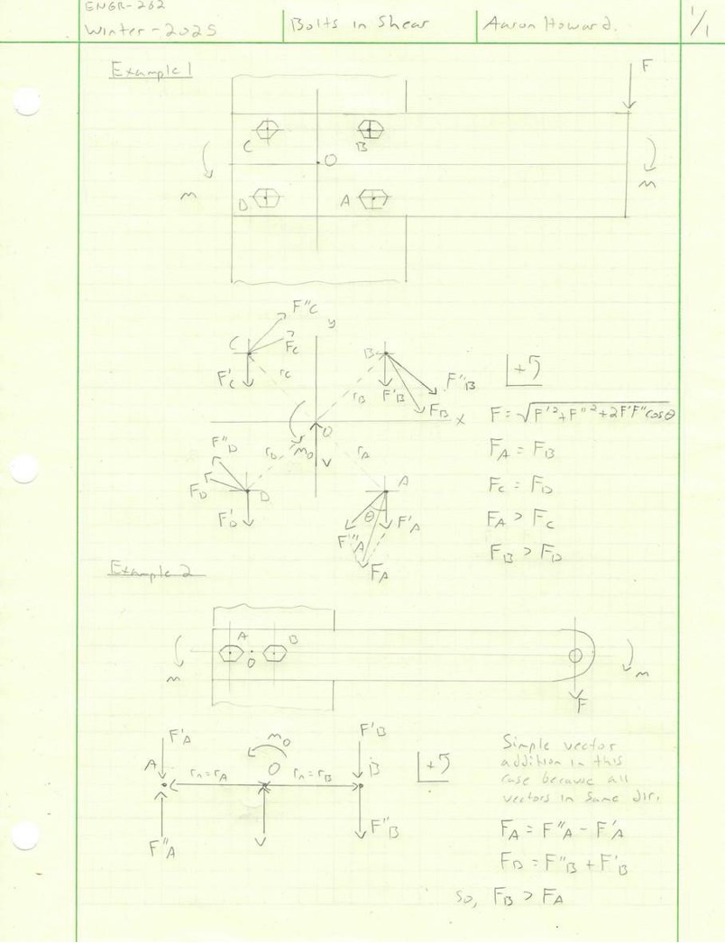
18.5.2 Riveted Joints and Bolts in Shear (Static)
When analyzing a bolt group or rivets in shear loading, the centroid of the bolt group must first be determined. Usually found by symmetry. The primary and secondary shear forces must next be found. The primary shear load per bolt (F’) is simply the shear force (v) divided by the number of bolts (n). The primary sheet load per bolt equation is shown below.
$$ F^{\prime} = \frac{v}{n} $$
The secondary shear force (F”) is calculated using the moment about the centroid caused by the external load and the radius from the origin to bolt being analyzed (rn). Typically, symmetry is present so 𝑟𝑛 = 𝑟𝐴 = 𝑟𝐵 … resulting in F” being equal for all bolts. The secondary sheer force equation is shown below.
$$ F^{\prime\prime} = \frac{M_{1}r_{n}}{r_{A}^{2} + r_{B}^{2} + …} $$
The point where a component or design is most likely to failure is always of upmost interest. Bolts and rivet groups are no different. Even though symmetry is typical with bolt groups, the external load creates a situation where the shear stress is likely not equal for each bolt. Determining the directions of the primary and secondary shear forces at each bolt is required to find the bolt that experiences the maximum stress. The direction of the primary shear force is simply the direction opposite the reaction force at the origin. The direction of the secondary shear force is opposite the reactionary moment at the origin and at 90 degrees from the radius that runs from the origin to the bolt of interest. The resultant shear force is found with trigonometry and by using the parallelogram rule:
$$ F = \sqrt{F’^{2} + F^{\prime\prime 2} + 2 F^{\prime} F^{\prime\prime} cos\Theta} $$
Note: The bolt experiencing the maximum shear force will be the bolt with the maximum shear stress if the bolt threads do not extend into the joint (preferred). If the bolt threads do extend into the joint, then the threaded portion of the bolt is subjected to the resultant shear force acting on the minor diameter. This increases shear stress, increasing the potential for failure which would occur along the minor diameter. The increased stress would be:
$$ \tau_{max} = \frac{F}{A} $$
A factor of safety should be used to indicate a potential for failure. This is a fractional value calculated by taking the allowable stress divided by an applied stress. The allowable stress used should be yield strength 𝑆𝑦 given bolts and rivets are made out of ductile steels. Shear yield strength 𝑆𝑠𝑦 predicted by the distortion energy theory is the most widely used theory for ductile materials.
$$ \tau_{max} = \frac{F}{A_r} $$
A factor of safety should be used to indicate a potential for failure. This is a fractional value calculated by taking the allowable stress divided by an applied stress. The allowable stress used should be yield strength (Sy) given bolts and rivets are made out of ductile steels. Shear yield strength (Ssy) predicted by the distortion energy theory is the most widely used theory for ductile materials.
$$ S_{sy} = 0.577S_y $$
$$ n = \frac{S_{sy}}{\tau_{max}} $$
A factor of safety value (n) less than one indicates failure.
18.5.3 Fatigue and Failure in Tension (Dynamic)
When analyzing fatigue failure, it is important to first determine if the loading and therefore the stress is completely revered. With bolts in tension, there is always the required preload condition, meaning the mean stress is never zero and a completely reversed condition is not the case. With a fluctuating (cyclical) loading cycle, the max, min, mean and alternating forces that each bolt experiences must be determined. The max is simply the total fluctuating load/#bolts and the min is the required preload condition.
The equation for Alt Stress is shown below:
$$ \sigma_{a} = \frac{C(P_{max} – P_{min})}{2A_t} $$
Mean Stress can be calculated using the equation below:
$$ \sigma_{m} = \frac{C(P_{max} – P_{min})}{2A_t} + \frac{F_i}{A_t} $$
Mean Stress can be written as a sum of Alt Stress and the load on each bolt:
$$ \sigma_{m} = \sigma_{a} + \sigma_{i} $$
Different failure criteria may be used.
Goodman Factor of Safety
The Goodman Factor of Safety (nf) can be calculated using the equation below:
$$ n_f = \frac{ S_e(S_{ut} – \sigma_i)}{\sigma_a(S_{ut} + S_e)} $$
The fully corrected endurance strength (Se) can be found in tables for bolts otherwise this can be found as the product of the endurance limit (S’e) and modifying factors for the given condition.
18.6 Assembly for Threaded Fasteners and Rivets/Eyelets
The effectiveness of threaded fasteners is dependent on how well the bolt or screw is seated against the part or surface to increase enough tension and therefore compression of the material between it to improve fatigue resistance. Effectiveness of a threaded fastener is achieved once preload has been met which is directly related to the amount of torque that is required to physically turn the fastener.
Torque can be applied by either operator feel, torque wrenches which measure the torque as the fastener is being turned, stall motors which cease applying torque once a specific value is reached (Groover 693) or torque-turn which tightens the fastener to a low torque level then rotates the fastener an additional specific amount (Groover 694).
Screws, nuts and bolts are the most important category of mechanical assembly. They are used everywhere from small electronic applications to large structures such as bridges.
Rivets are applied with either compression or impact using either a pneumatic hammer to deliver successive blows or steady compression by a riveting tool which applies a continues squeezing pressure. Equipment used for riveting is usually portable, manually operated and automatic. (Groover 694) Rivets are used in gutters, automotive bodywork and aerospace to reduce drag. Despite the advantages of rivets such as high production rates, simplicity, dependability and low cost, rivets have been slowly replaced over the years in favor of threaded fasteners, welding and adhesive bonding.
Eyelets are substituted for rivets in low-stress applications to save material, weight and cost (Groover 694). They are typically used in small electrical components and automotive subassemblies, toys and apparel.
18.7 Assembly for Interference Fits
A common press fit is the fitting of a pin or shaft inserted onto a collar. It is important to compare the maximum effective stress which occurs in the collar at its inside diameter to the yield strength of the material. Press fits are used in high-stress situations, such as in automotive and industrial machinery.
Assembling with shrink and expansion fit methods can be achieved with heating equipment such as electric resistance heaters, torch furnaces and electric induction heaters. Cooling methods include conventional refrigeration, packing in dry ice and immersion in cold liquids such as liquid nitrogen. (Groover 697) Shrink and expansion fits are used anywhere a strong mechanical connection is required without the use of additional fasteners such as wheels on axels or turbine blades attached to hubs.
Snap fit assembly is simply the operator joining the two parts by applying the necessary pressure for temporary elastic deformation to occur. Continued increased pressure allows the two parts to be mated (snapped) together which allows them to return to their original shape. Snap fit joints are commonly used in consumer products. They are used throughout the automotive industry from headlight assemblies to dashboard assemblies as well as in consumer electronics from remote controls to laptops.
18.8 Chapter Summary
Having a knowledge of the various fastening methods is important for any person who is interested in mechanical engineering. The variety of fasteners is overwhelming and while this chapter cannot cover all the types it has covered some of the most common methods and assembly for non-permanent joints, permanent joints and interference fits. Bolts, screws and rivets are most commonly used in industry due to their ease of use and versatility. An introduction to design analysis is included in this chapter that pertains to threaded fasteners and rivets in common static and dynamic situations. Improving bolt reliability is highly dependent on finding the proof strength listed in tables and implementing the proper preload. Other important mechanical properties for threaded fasteners include finding the tensile stress area and yield strength listed in tables. There will always be a need for fasteners and understanding how they perform is crucial for a quality design.
18.9 References
Groover, Mikell P. Fundamentals of Modern Manufacturing: Materials, Processes, and Systems. 7th ed., Wiley, 2020.
Budynas, Richard G. Nisbett J. Keith. Shigley’s Mechanical Engineering Design. 11th ed., McGraw-Hill Education, 2020.
“File:Screw Threads 2.Png – Wikimedia Commons.” Wikimedia.org, 16 Nov. 2011, commons.wikimedia.org/wiki/File:Screw_Threads_2.png. Accessed 5 Feb. 2025.
“File:Square Thread Form.svg – Wikimedia Commons.” Wikimedia.org, 16 Dec. 2008, commons.wikimedia.org/wiki/File:Square_thread_form.svg. Accessed 5 Feb. 2025.
“File:Ensamblaje Snap-Fit.jpg – Wikimedia Commons.” Wikimedia.org, 22 Apr. 2011, commons.wikimedia.org/wiki/File:Ensamblaje_snap-fit.jpg. Accessed 5 Feb. 2025.
“File:Direct Riveting.png – Wikimedia Commons.” Wikimedia.org, 29 Jan. 2012, commons.wikimedia.org/wiki/File:Direct_riveting.png. Accessed 6 Feb. 2025.
“File:Copper-Press-Fitting.JPG – Wikimedia Commons.” Wikimedia.org, 9 Dec. 2015, commons.wikimedia.org/wiki/File:Copper-press-fitting.JPG. Accessed 20 Feb. 2025.
Jensen, David . Introduction to Mechanical Design and Manufacturing . University of Arkansas Libraries, uark.pressbooks.pub/mechanicaldesign/. Accessed 5 Feb. 2025.
Culpepper, Martin . “Resources | Elements of Mechanical Design | Mechanical Engineering | MIT OpenCourseWare.” MIT OpenCourseWare, 2025, https://ocw.mit.edu/courses/2-72-elements-of-mechanical-design-spring-2009/download/. Accessed 5 Feb. 2025.
“File:Screw Thread Forms.png – Wikimedia Commons.” Wikimedia.org, 2022, commons.wikimedia.org/wiki/File:Screw_thread_forms.png, https://doi.org/1019928.n3. Accessed 20 Feb. 2025.
Media Attributions
- UNF Threads © Robert Hewitt is licensed under a CC BY-SA (Attribution ShareAlike) license
- seven common screw threads © Carl Lars Svenson is licensed under a Public Domain license
- Square thread form © Wizard191 is licensed under a CC BY-SA (Attribution ShareAlike) license
- Bolted_joint_with_nut.svg © Андрей Перцев is licensed under a Public Domain license
- Direct riveting © W.Rebel is licensed under a CC BY-SA (Attribution ShareAlike) license
- Direct riveting © W.Rebel is licensed under a CC BY-SA (Attribution ShareAlike) license
- press fit pipes © Cschirp is licensed under a CC BY-SA (Attribution ShareAlike) license
- Ensamblaje snap-fit © Silvia Climent is licensed under a CC BY-SA (Attribution ShareAlike) license
- Bolts in Sheer © Aaron Howard is licensed under a CC BY-SA (Attribution ShareAlike) license
